Wearable Computing
Introduction to Arduino Lilypad
Arduino IDE
Setup & Installation
Getting Started with

The Arduino LilyPad is a fun, easy to use wearable computer. Similar to the Adafruit Flora--another popular e-textiles electronics platform--the LilyPad can be paired with sensors, switches, LED lights, and other modules to create a wide array of innovative clothing and fabric projects.
We'll be using the Arduino IDE we just installed to program our LilyPad. Code for many wearable computing projects is freely available on the web, and a good starting point to developing projects for the LilyPad is copying and adapting existing code to fit your needs.
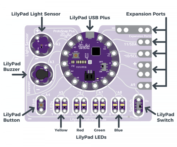
For our projects we'll be using the Arduino LilyPad ProtoSnap Plus. These innovative boards come with preassembled circuits connecting to a light sensor, a buzzer, 15 leds, a button, and a switch. We'll be leaving the boards fully assembled through the duration of this tutorial, which will allow us to easily develop and test our projects without worrying about sewing. As you develop your prototype, only snap apart the ProtoSnap kit and begin sewing once you've fully tested, vetted, and approved your code.
In this guide, we'll be:
- Blinking the onboard LEDs
- Linking additional LEDs
- Buzzing the buzzer
-Adding a button
- Exploring the Light Sensor
Blinking the Onboard and External LEDs
For this first activity, we'll begin by working with the LEDs that are built into the LilyPad Plus. In addition to an on-off switch and a reset button, the LilyPad Plus features six white LEDs and a RGB LED onboard.
First, we'll blink the onboard LED. Copy the following code into the Arduino IDE:
    // Pin 18 has a LED connected on ProtoSnap Plus.
    // give it the name 'led':
    int led = 18;

    // the setup routine only runs once on power up, or when the reset button is pressed.
    void setup() {
      // initialize the digital pin as an output.
      pinMode(led, OUTPUT);
    }

    // the loop routine runs over and over again forever as long as there is power and no errors:
    void loop() {
      digitalWrite(led, HIGH);   // turn the LED on (HIGH is the voltage level)
      delay(1000);               // wait for a second
      digitalWrite(led, LOW);    // turn the LED off by making the voltage LOW
      delay(1000);               // wait for a second
    }
To light up the external LEDs, copy the following code into the Arduino IDE:
// Again, we'll assign the pins we're working with a name.
int led1 = A5;
int led2 = A7;
int led3 = A8;

// the setup routine runs only once on power up, or when reset button is pressed.
void setup() {
  // initialize the digital pin as an output.
  pinMode(led1, OUTPUT);
  pinMode (led2,OUTPUT);
  pinMode (led3, OUTPUT);
}


// the loop routine runs continually:
void loop() {
  digitalWrite(led1, HIGH);   // turn each LED on (HIGH is the voltage level)
  digitalWrite(led2, HIGH);
  digitalWrite(led3, HIGH);
  delay(1000);               // wait for a second
  digitalWrite (led1, LOW);  // turn each LED off by making the voltage LOW
  digitalWrite (led2, LOW);
  digitalWrite (led3, LOW);

  delay(1000);               // wait for a second
  digitalWrite(led1, HIGH);
  delay(500);               // wait for half a second
  digitalWrite(led1, LOW);
  digitalWrite(led2, HIGH);
  delay(500);
  digitalWrite(led2, LOW);
  digitalWrite(led3, HIGH);
  delay(500);
  digitalWrite(led3, LOW);
  delay(500);
}
Blinking onboard LED code courtesy of Adafruit. Neopixel code courtesy of Andy Boyles Petersen.
Sensors, Sounds, and Switches

Now that we've worked with the onboard LilyPad ProtoSnap Plus lights, as well as external LEDs, we can move on to adding additional components. Shown above is a component display of the ProtoSnap Plus kit. Each component is connected to a different build-out pin, with multiple slots for additional expansions. In the last exercise, we used build-out pins A5, ~A7, and ~A8 to connect yellow, green, and blue LEDs.
In addition to the build-out pin connections, each component is linked back to a negative (-) grounding pin. For more complex components, such as the light sensor, you'll notice a separate positive (+) pin connection. For these, the positive (+) pin is providing power, with the build-out pin exclusively providing commands for the component.
Now, we'll make the buzzer play a series of tones. Once you've got it down, try writing your own tune! Copy the following code into the Arduino IDE:
// Create an integer variable naming the pin we'll use for the buzzer.
// On the ProtoSnap Plus, it's on A3.

int buzzer = A3;

// Map musical notes to their frequencies by creating variables for them.
// You can find the frequencies for higher and lower notes at:
// https://www.arduino.cc/en/Tutorial/toneMelody

int NOTE_C5 = 523;
int NOTE_CS5 = 554;
int NOTE_D5 = 587;
int NOTE_DS5 = 622;
int NOTE_E5 = 659;
int NOTE_F5 = 698;
int NOTE_FS5 = 740;
int NOTE_G5 = 784;
int NOTE_GS5 = 831;
int NOTE_A5 = 880;
int NOTE_AS5 = 932;
int NOTE_B5 = 988;
int NOTE_C6 = 1047;

// We'll also create a variable for how long to play each note in milliseconds.
// If you make this smaller, the notes will play faster.

int tempo = 500;

void setup()
{
  // Set the buzzer pin to be an output:

  pinMode(buzzer, OUTPUT);
}

void loop()
{
  // This code will play a simple scale from C5 to C6.

  // The tone command takes two parameters: a pin number and a frequency.
  // The tone will play until we stop it with the noTone command.
  // Each of the below blocks plays one note; the note plays during the delay command.

  tone(buzzer,NOTE_C5);
  delay(tempo);

  tone(buzzer,NOTE_D5);
  delay(tempo);

  tone(buzzer,NOTE_E5);
  delay(tempo);

  tone(buzzer,NOTE_F5);
  delay(tempo);

  tone(buzzer,NOTE_G5);
  delay(tempo);

  tone(buzzer,NOTE_A5);
  delay(tempo);

  tone(buzzer,NOTE_B5);
  delay(tempo);

  tone(buzzer,NOTE_C6);
  delay(tempo);

  // A longer delay at the end pauses the sound before looping again.
  // Here we're delaying four times the "tempo" value:

  noTone(buzzer);
  delay(tempo * 4);

  // You can change the note duration by multiplying or dividing the "tempo" value
}
Next, we'll add a bit more complexity by incorporating a button to turn your tune on and off. Once you've succeeded with the button, try instead using the switch. Copy the following code into the Arduino IDE:
// Create an integer variable naming the pins we'll use for the buzzer and button.

int buzzer = A3;
int button = A4;

// Map musical notes to their frequencies by creating variables for them.
// You can find the frequencies for higher and lower notes at:
// https://www.arduino.cc/en/Tutorial/toneMelody

int NOTE_C5 = 523;
int NOTE_CS5 = 554;
int NOTE_D5 = 587;
int NOTE_DS5 = 622;
int NOTE_E5 = 659;
int NOTE_F5 = 698;
int NOTE_FS5 = 740;
int NOTE_G5 = 784;
int NOTE_GS5 = 831;
int NOTE_A5 = 880;
int NOTE_AS5 = 932;
int NOTE_B5 = 988;
int NOTE_C6 = 1047;

// We'll also create a variable for how long to play each note in milliseconds.
// If you make this smaller, the notes will play faster.

int tempo = 500;

void setup()
{
  // Initialize the button as an input with pullup.
  // Pullups keep the inputs from 'floating' when a switch or button is open/unpressed.
  pinMode(button, INPUT_PULLUP);

  // Initialize the buzzer as an output.
  pinMode(buzzer, OUTPUT);
}

void loop()
{
  // This code will read the positions of the button,
  // then use the 'if' command to make LEDs follow these states.

  // Create variables to store the button input value:
  int buttonState;

  // Read and save the states of the button:
  buttonState = digitalRead(button);

  // The if-else statement lets you do different things based on different inputs:
  // The button will read as LOW when it's pressed

  if (buttonState == HIGH) // Check to see if buttonState is HIGH (unpressed) //
  {
    noTone(buzzer);
  }

  else
  {
    tone(buzzer,NOTE_C5);
    delay(tempo);

    tone(buzzer,NOTE_D5);
    delay(tempo);

    tone(buzzer,NOTE_E5);
    delay(tempo);

    tone(buzzer,NOTE_F5);
    delay(tempo);

    tone(buzzer,NOTE_G5);
    delay(tempo);

    tone(buzzer,NOTE_A5);
    delay(tempo);

    tone(buzzer,NOTE_B5);
    delay(tempo);

    tone(buzzer,NOTE_C6);
    delay(tempo);

    // A longer delay at the end pauses the sound before looping again.
    // Here we're delaying four times the "tempo" value:

    noTone(buzzer);
    delay(tempo * 4);
  }

}
Lastly, we'll incorporate the light sensor, using the sensor to light up LEDs. Copy the following code into the Arduino IDE:
// Create variables for the pins we'll use:

int LightSensor = A2;

int redLED = 6;
int greenLED = A7;
int blueLED = A8;

void setup()
{
  // Initialize the sensor pin as an input, but without a pullup
  // (Pullups are only used for switch inputs)

  pinMode(LightSensor, INPUT);

  // Initialize the output pins:

  pinMode(redLED, OUTPUT);
  pinMode(greenLED, OUTPUT);
  pinMode(blueLED, OUTPUT);

  // Initialize the serial monitor:

  Serial.begin(9600);
}

void loop()
{
  int sensorValue;

  // Read the sensor value (will be 0 to 1023):

  sensorValue = analogRead(LightSensor);

  // Print out the sensor reading to the serial monitor:

  Serial.print("sensor value: ");
  Serial.println(sensorValue);

  // Since the sensor value is 0 to 1023,
  // and analogWrite needs a value from 0 to 255,
  // we'll divide the sensor value by four to scale it down:

  analogWrite(redLED,sensorValue / 4);
  analogWrite(greenLED,sensorValue / 4);
  analogWrite(blueLED,sensorValue / 4);
}
Buzzer tune scale code courtesy of Sparkfun 'Play a Tune' tutorial. Buzzer button code by Andy Boyles Petersen, adapted from Sparkfun. Light sensor code courtesy of Sparkfun 'Sensing Light' tutorial.
Developing Your Prototype
Now that we know the basics of working with the Arduino LilyPad ProtoSnap Plus, we're going to put our new found skills to use in developing our prototypes. Consider elements such as color, solid vs. blink, light duration, tone, etc., and craft your code to best fit your prototype's needs. In considering the design of your prototype, keep in mind this is a proof of concept--not necessarily a final build. Many completed wearable projects require more elements, such as different sensors, bluetooth or wifi connectivity, or actuators. If you feel these additional elements would enhance your prototype, be sure to describe how you would incorporate them in your reflection. As with your apps, this wearable prototype should be well thought out and functional, even without additional supporting elements.
If you need further inspiration, or additional code sets, consider looking at Sparkfun's LilyPad ProtoSnap Plus Activity Guide, Sparkfun's other LilyPad ProtoSnap tutorials, Adafruit's sample Flora projects, as well as Flora user guides/tutorials.
Understanding Circuits and Sewing


Circuits
Your circuit will always begin with a build-out pin (ex. A4, A5, ~A9). For many lights and sensors, this terminal will also serve as your positive (+) power terminal. Some sensors and modules, such as the Light Sensor, will require a separate power connection from the build-out pin, as shown on your LilyPad.
- From the build-out pin, form a chain and connect to the (+) terminal on your first LED or other component.
- The negative (-) terminal will continue your chain, reaching out to connect with the (+) terminal on your next component.
- Once you've linked all your components, complete the chain by connecting to the negative (-) pin on the LilyPad.
Be sure to take note of the positive and negative terminals; they always need to be connected in the proper orientation!
There are two basic ways to connect circuit components--in series and in parallel.
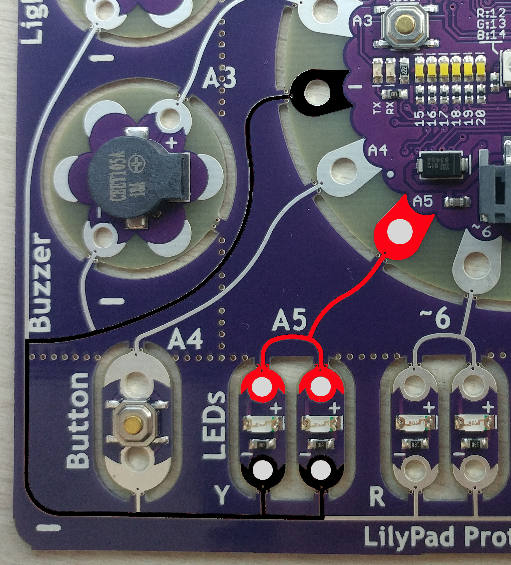
The top image on the left shows a LilyPad ProtoSnap, highlighting the thread path for wiring LEDs in parallel. Parallel circuits provide electrons more than one continuous path to flow through. Both current paths lead from pin A5 (our source of power) to the LEDs positive (+) terminal, then out from the negative (-) terminal into the negative ground pin on the LilyPad.
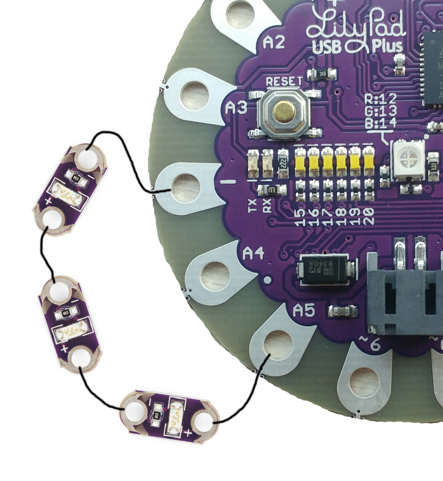
The second image on the left shows the thread path for wiring LEDs in series. Series circuits are the most basic circuit, providing electrons one continuous path through the circuit. Starting with the A5 buildout terminal, this series circuit flows through three LEDs, connecting (+) to (-) on each and ending on the LilyPad's (-) ground pin.
Sewing
Once you have have a completed code set for your prototype, test it out on your ProtoSnap Plus. Be sure to fully vet your code set before snapping out your ProtoSnap; testing code becomes significantly more difficult once the board is ProtoSnap is taken down into its individual components. When you are fully comfortable with your code set, snap apart one group member's ProtoSnap. Be careful to not apply too much force, and only snap along the designated seams. At this point, you're ready to begin sewing. In sewing your ProtoSnap into a project, be sure to consider polarity, power, adequate support, and functionality.
A few preliminary tips:
- Sew over your seams multiple times. Our conductive thread is quite thin, and doubling up your seams will ensure proper function.
- Do not cross threads! It is quite easy to short out your circuit, particularly if sewn too close. Design your project to ensure you won't be.
- Consider the physical nature of your project. If it will see significant movement in use, leave extra flex in your seams. If it's worn next to the skin, consider your user's comfort.
- Consider other conductive devices. If you're using snaps or metal fasteners, these conductive materials either need to be protected against shorting out your wiring or incorporated into your circuit.